Counter - ZählwerkThis page documents the connection of a prototype SpDrS60 counter device to the panel IO board for control over LocoNet. Contents
Disassembled counter device
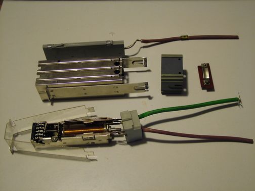
The foto shows a counter device (Zählwerk) in a SpDrS60 table disassembled. The middle shows the chassis that holds all other pieces together. To the right next to it is a plactic case that holds the pull relief to the right of it. Above the metal chassis is a slim plastic box that has one row of three standard SpDrS60 slots for buttons or bulbs on the left side (which is the table top side) - on the right side you see the two wires connected to the middle slot that will be used for a button. There are two such plastic boxes, one on each side of the actual counter.
Below the metal chassis is the core element, the counter mechanism.
The transparent plastic to the left is wrapped around it and protects the
table top side. The plastik block on the right seems to have a mechanic
role. The obvious magnet coil moves a metal plate that is held in its
idle position by a spring. The plate operates the counter mechanism and
two contacts. Above the coil on the picture is an opening contact, below
is a closing contact. The wires to the right are bundled as two wires
for the closing contact (brown) and four wires for opening contact and
coil (green) Design of the boardFor several reasons I decided to develop a dedicated board for control and monitoring of the counter devices via LocoNet. Main design drivers are:
Design files:
On the left side you see the processor with ISP and TTL level LocoNet connectors as similarly used in the panel I/O board. On the top is shown how I intend to generate the 60V DC from 12V DC that is used to run the indicator bulbs in the table. I run two 12V to +-15V DC/DC converters in serial. The fuse shall be the smallest PTC fuses that Reichelt offers (PFRA 010) Six identical connectors CNTR1..6 are intended for the counters. The coil is connected between pins 1 and 2. The coils are driven by dedicaded discrete transistors, because those are the only small ones that I found that can stand 60V. The ULN driver of the panel I/O board is not rated high enough. The opening contact is connected between pins 4 and 3, the closing contact between pins 4 and 5. It may seem strange to connect both contacts. But I still dream of simulating the rest of the relay plant in software on a circuit level. I might want to have both contacts in hardware later on...

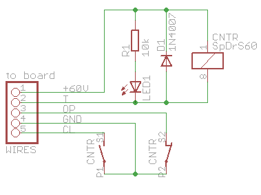
Wireing the board with the counterThe circuit that is soldered into the bottem compartment of the counter device is shown to the right. The diode indeed is redundant with the one on the board. I could not decide where to place it, so I did it on both sides ;-)
|